

![]() By Agenor Garcia* and Bruce Rowse**
By Agenor Garcia* and Bruce Rowse**
This is part II of the article published in the October 2018 issue of M&V Focus.
5. Modelling
Now let’s generalise the concepts presented in these examples to take a broader view of the issue.
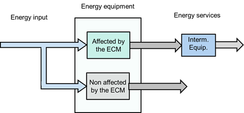
Figure 8 - Modelling the boundary challenge
We are dealing with energy flows, with:
- An input of energy;
- Equipment that uses energy to provide energy services (some affected by ECM and others not); and
- Energy services, whose control affects the flow of energy through the boundary. As the examples earlier illustrated, the conversion of energy into energy services can pass through intermediate phases, which can also be used to evaluate the energy savings provided by ECM.
For example, energy flows associated with a chiller are:
- An electricity supply;
- The chiller converts the energy to produce chilled water;
- Pumps, fans and heat exchangers convert the chilled water to chilled air;
- Chilled air provides comfort (the energy service).
Table 2 presents a few examples demonstrating the concept of energy being transferred into energy services.
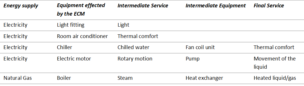
Table 2 - Examples of the conversion of energy into a service
Some energy services pass through intermediate stages others do not. In the case of direct expansion air conditioning, refrigerated air could be considered as an intermediate service as well. There are, therefore, various ways to measure energy use and the independent variables in order to conduct M&V. This is illustrated in figures 9 and 10 below, which shows possible metering points.
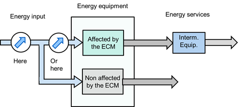
Figure 9 - Metering of energy
Energy meters can measure only the equipment affected by the ECM, which would be Options A and B of the IPMVP, or it can measure usage of the whole facility, which would be Option C.
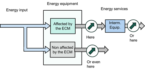
Figure 10 - Measuring the independent variables
The measurement of the independent variables can be:
- That which affects end use (eg, external temperature and occupancy affect environmental conditioning, or production affects the gas that feeds the boiler).
- That of an intermediate variable (in the examples above, the chilled water in a water-based air conditioning system, and steam in the boiler).
- Or even in services not covered by the ECM (for example, a major upgrade of a building's lighting can be measured by Option C, but the energy baseline is explained by the use of air conditioning, since the lighting is practically fixed).
Thus we can define three major approaches to defining the measurement boundaries, as discussed below.
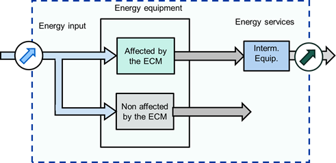
Figure 11 – Approach 1 - Measurement boundary - whole facility
The first approach would be to consider the whole facility, the energy utility meter for the whole site and the measurement of the variables that significantly affect the energy service. The advantages of this approach are: the baseline is already available because the input data comes from the energy bill and the output data is usually already collected by the facility owner; no additional measurement costs; the variation of energy and economy are directly related to variables currently understood by the owner. The disadvantages: there are many static factors: both those related to equipment not affected by ECM, and those related to the configuration of the installation. This option, therefore, is focused on the whole site.
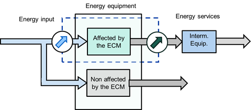
Figure 12 - Tight Measurement boundary (equipment)
At the other extreme is the approach focused on the equipment. Energy measurements are undertaken on the energy supply to the affected equipment and the independent variable is the output of the equipment (chilled water in the chiller, steam in the boiler, pump flow, etc.). The measurement costs are high, but this enables excellent feedback on the impact of any changes, and there are few static factors.
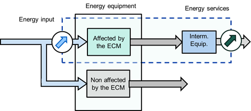
Figure 13 - Approach with an intermediate measurement boundary
Between these two approaches, there is a middle way, which consists of the measurement at the energy input into the equipment (Option B or A) but correlates this with the independent variables related to the entire site.
The advantage over the first approach (measuring energy across the entire installation) is that there are fewer static factors, represented by the equipment not affected by the ECM. The disadvantage is that a meter still needs to be installed, and time is required to measure the baseline. In relation to the second approach (narrow boundary), the advantage is that the variations of energy and economy are explained by characteristic variables of the site – usually well understood by the facility managers/owners; the downside is that it has to take into account static factors across the entire site.
6. Another interesting example
Another example (proposed by John Cowan) that illustrates well the measurement boundary issue is the one below, which deals with an ECM in a furnace, which takes advantage of the residual heat of the combustion by means of a heat recovery heat exchanger installed in the chimney.
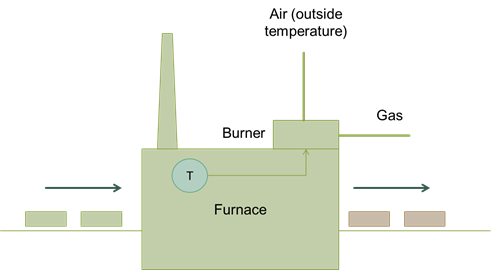
Figure 14 - Furnace before implementation of the ECM
Figure 14 shows the baseline conditions: the oven is heated by gas, with outside air providing the oxygen for combustion. A control system keeps the temperature constant inside the oven. A fan in the burner forces the circulation of air in the furnace, whose waste gases exit the chimney, at an elevated temperature. A conveyor belt moves metal components through the furnace, which are being heated so that they can subsequently be forged into automotive components.
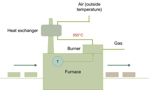
Figure 15 - Furnace after implementation of the ECM
With the installation of a heat exchanger, the combustion air is preheated to 550 ⁰C, reducing the need for heat in combustion and reducing gas consumption. Of course, to size the heat exchanger, it is necessary to estimate the air flow and the temperatures at the entrance and exit of the heat exchanger. In this phase of ECM "analysis", the heat exchanger efficiency and the impact of the air temperature change on the combustion and the reduction in gas demand are also estimated. It is natural that the specialists involved in this engineering phase want to see how the equipment performs and may propose the following M & V structure:
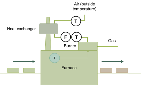
Figure 16 - Approach 1 to M&V
Placing temperature sensors at the entrance and exit of the heat exchanger and measuring the air flow would enable the measurement of the heat supplied to the combustion air. However, M & V's question is not whether the exchanger is working well, it is “how much gas has been saved?”. Thus we would either undertake more measurements or make the "best possible" estimates in order to determine the reduction of gas consumption. Since we want to know the gas reduction, why not measure gas consumption directly? And as the variation in consumption depends on production, production would be measured as well.

Figure 17 - Second approach to M&V
With the measurement of gas consumption and furnace production, the baseline model can be established and the avoided gas consumption in the reporting period can be calculated by subtracting the gas consumption from that calculated using the baseline model.
Since the measurement limits are the gas meter and the production, one can draw the measurement boundary as shown in Figure 17.
Another consideration is the energy used by the fan drawing air through the heat exchanger. If the boundary is not viewed in terms of the flow of gas energy (gas – hot air – heating of the metal pieces – heating of the incoming air with the flue gas), the fan can be seen as being located within the measurement boundary.
However, as it is powered by electricity, this flow is obviously out of the measurement boundary, which measures only gas and production. If calculations showed that this was likely a significant interactive effect, the energy boundary could be adjusted to include both natural gas flows into the furnace, and electricity flows into the fan, with an electricity meter installed on the energy supply to the fan.
[END OF PART II]
REFERENCES
EVO – Efficiency Valuation Organisation. Core Concepts, International Performance Measurement and Verification Protocol, 2016.
GERBI – Greenhouse gas Emissions Reduction in Brazilian Industry. M&V Case Study: Heat Recovery in a Furnace, power point presentation, Rio de Janeiro, 2003. Based on a problem initially proposed by John Cowan.

(*) Agenor Garcia is an energy efficiency and M&V consultant based in Brazil, technical director of CTC Experts. Agenor is a member of EVO's Extended Training Committee and an EVO L3 accredited instructor.

(**) Bruce Rowse is a consultant with 8020Green and is based in Australia. Bruce is the chairman of EVO's Extended Training Committee and an EVO L3 accredited instructor.